Uzone Group does quality control on glass cosmetic containers during the whole production flow.
Purpose of detection on glass cosmetic containers
Standardize the size of bottles and cans of packaging materials testing projects and defect categories.
Scope
All glass cosmetic containers need to measure the size of bottles and jars of packaging materials, such as cosmetic plastic bottles, cosmetic plastic jars, cosmetic glass bottles, cosmetic glass jars, etc.
Instruments and equipment
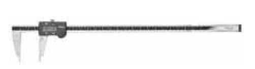
(1) Vernier calipers (scale type precision 0.02mm, with digital display can be estimated to read the accuracy of 0.01mm).
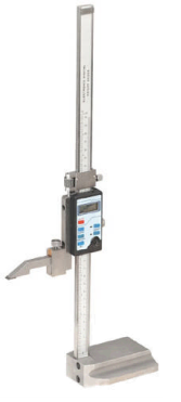
(2) Height ruler (scale type accuracy 0.02mm, with digital display can be estimated to read the accuracy of 0.01mm).
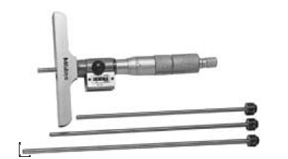
(3) Depth ruler (scale type accuracy 0.02mm, with digital display can be estimated to read the accuracy of 0.01mm).
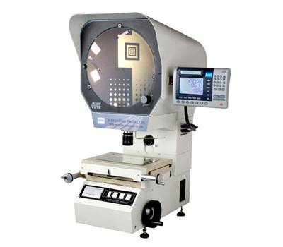
(4) Projector (suitable for measuring transparent materials or material outline, accuracy and magnification).
(5) Feeler gauge (suitable for measuring the gap size such as segment difference).
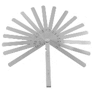
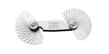
(6) R gauge (radius gauge, suitable for measuring rounded corners).
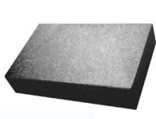
(7) Marble plate.
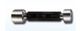
(8) Go-No-Go.
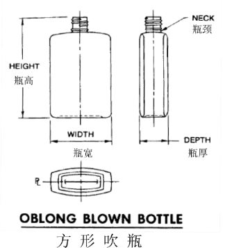
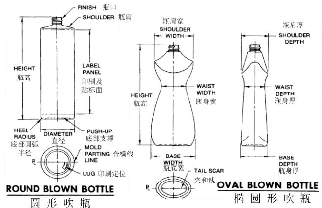
Professional terminology
(Terminology for each part of the cosmetic glass bottles)
Common codes
Bottle size terminology
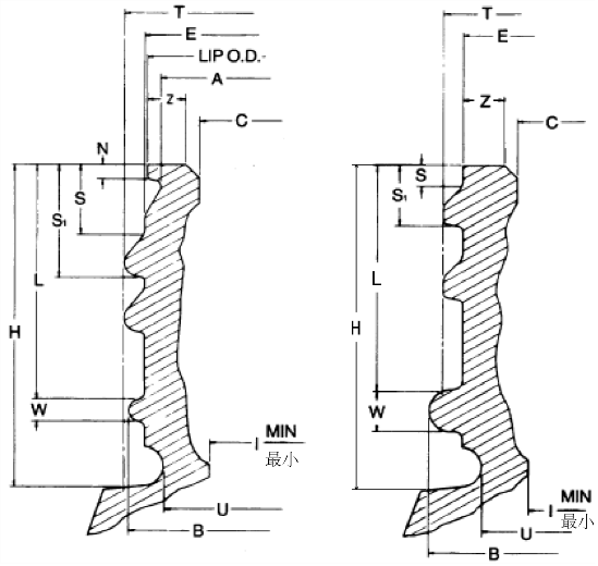
(1) A – Outside diameter of the lower mouth of the bottle edge.
(2) B – Outside diameter of the positioning ring.
(3) C – The inner diameter of the opening at the top of the bottle mouth (sometimes called the I size).
(4) E – The outer diameter of the bottle wall at the root of the screw thread, also called the small diameter of the screw thread or the bottom diameter of the screw thread.
(5) H – The vertical dimension from the top of the bottle mouth to the positioning ring or shoulder, also called the neck height.
(6) I – The smallest opening through the mouth and neck of the bottle (sometimes called the smallest I).
(7) L – The minimum vertical distance from the top of the bottle mouth to the top edge of the positioning ring.
(8) N – The thickness of the vertical bottle mouth rim, used for pouring or capping fits.
(9) S – The vertical distance from the top of the bottle mouth to the top of the threaded starting tooth.
(10) S1 – The vertical distance from the top of the bottle mouth to the bottom of the threaded capping teeth (mainly used for cap positioning).
(11) S2 – The vertical distance measured from the top of the bottle mouth to the top surface of the screw thread after rotating 90° counterclockwise from the S measurement point.
(12) T – The outer diameter of the screw thread, also called the large diameter of the screw thread.
(13) U – The outer diameter of the lower cutout (optional).
(14) W – Positioning ring width.
(15) Z – Width of sealing surface.
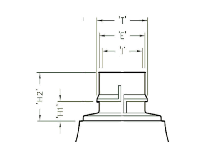
(16) H1 – The distance from the lower end of the gland snap ring to the shoulder of the bottle.
(17) H2 – The height from the top of the bottle mouth to the shoulder of the bottle.
Testing steps
(1) development stage: each hole to take three representative samples to be tested. Inlet inspection stage: GB/T 2828-2012 counting sampling and inspection procedures of the normal primary sampling program sampling.
(2) (2) The product is placed at 23℃/50%RH environment for 24 hours.
(3) (3) Measurement of “H” dimension: Place a depth ruler through the center of the bottle mouth, not along the mold line, make the caliper core contact with the threads, extend the caliper core to make contact with the shoulder or positioning ring of the bottle, and measure the height of the bottle mouth (as shown below). Rotate the bottle under the caliper by 360° to determine the maximum and minimum readings, and record the maximum and minimum dimensions.
(Measurement of “H” size)
(4) Measurement of “H1″ size: Measure the distance from the lower end of the gland insertion ring to the top of the bottle shoulder with an optical projector.
(5) (5) Measurement of “H2″ size: Measure the distance from the top of the bottle mouth to the top of the bottle shoulder with an optical comparator or depth gauge.
(6) ”S” size measurement: put the bottle on the platform so that the bottle mouth is placed under the foot of the height gauge, lower the foot so that it just touches the top surface of the bottle mouth above the starting teeth, and record the height; lower the foot so that it just separates the upper circle radius between the corner of the screw tooth at the starting teeth and the E wall of the bottle mouth, and record the height (the following figure). Subtract the two height values and record the result as S.
(Measurement of “S” size)
(7) “S1″ size measurement: put the bottle on the platform so that the bottle mouth is placed under the foot of the height gauge, lower the foot so that it just touches the bottle mouth above the starting teeth, record the height; then install the foot as shown in the dashed line (below), raise the foot until it just separates the lower circle arc between the corner of the screw tooth and the wall of the bottle mouth E at the starting point of the full tooth. Radius, record the height. Subtract the two height values and record the result as S1 value.
(Measurement of “S1″ size)
(8) Measurement of “S2″ size: Place the bottle on a flat plate, rotate 90° counterclockwise from the S positioning point and place the bottle mouth under the foot of the height gauge (as shown below), record the height; then lower the foot so that it exactly touches the top surface of the thread, and record the result as the S2 value.
(Measurement of “S2″ size)
(9) Measurement of “L” dimension: put the bottle on the platform, place the bottle mouth under the caliper of the height gauge, lower the caliper so that it is in contact with the lowest point of the top surface of the bottle, and record the height; lower the caliper foot so that it is exactly separated from the radius of the upper circle between the positioning circle and the E wall, and record the height (as shown below). Subtract the two values and record the result as L value.
(“L” size measurement)
(10) “N” (bottle edge thickness) size measurement: use the caliper blade to measure the bottle edge thickness at the thickest edge of the outer diameter (not on the closing line), (the following figure), record the results. Do not squeeze the caliper and deform the edge of the bottle.
(Measurement of “N” size)
(11) Measurement of “T” dimension: Close the calipers until the measuring surface touches the threads, and make sure the measuring surface is parallel to the core of the bottle mouth; rotate the bottle 180° to determine the main and secondary axes (do not measure on the clamping line), (as shown below), and record the readings measured along the main and secondary axes respectively. The average value along the main and secondary axes is the T value.
(Measurement of “T” dimension)
(12) Measurement of “E” dimension: Close the caliper until the measuring surface touches the E diameter of the thread root (as shown below), rotate the bottle 180° to determine the main and secondary axes (do not measure on the die line, as the measurement error caused by the tilting of the card angle due to the presence of the spiral can be ignored), and record the readings of the main and secondary axes. The average of the main and secondary axis readings is the E value. Note: The E dimension can be measured at different locations in the thread area.
(Measurement of the “E” dimension)
(13) “B” (outside diameter of positioning ring) dimension measurement: Close the caliper so that the measuring surface of the caliper is in contact with the B diameter (as shown below), rotate the bottle 180° to determine the main axis and the secondary axis (do not measure on the die line), and record the main and secondary axis readings. The average of the main and secondary axis readings is the B value.
(Measurement of “B” size)
(14) “U” dimension measurement: Close the caliper until the caliper cutter touches the U diameter (as shown below), rotate the bottle 180° to determine the primary and secondary axes (do not measure on the die line), and record the primary and secondary axes readings. The average of the primary and secondary axis readings is the U value.
(Measurement of “U” dimension)
(15) “A” (the outer diameter of the lower mouth of the bottle edge) measurement: close the caliper until the caliper blade touches the diameter of “A” (as shown below), rotate the bottle 180° to determine the main and secondary axes (do not measure on the mold line), and record the readings on the main and secondary axes. The readings on the primary and secondary axes are recorded. The average of the readings on the primary and secondary axes is the size A value.
(Measurement of dimension “A”)
(16) “C” (inside diameter of the top opening of the bottle, sometimes referred to as the I size) size measurement: extend the foot into the inside of the bottle mouth more than 3mm, (the following figure), open the card angle until the measuring surface and the “C” size (position) contact, rotate the bottle 180 ° Determine the primary and secondary axes, and record the average of the readings in the primary and secondary axes as the C value. In addition, there is another important parameter in this measurement: ellipticity. The ellipticity value is the difference between the readings in the primary and secondary axes.
(“C” size of the measurement)
(17) “I” (through the bottle mouth and neck of the smallest opening) size measurement: insert the stopper gauge into the bottle mouth, the stopper gauge should be able to pass unimpeded throughout the bottle opening, (the following chart), to pass or not pass or the smallest I inside diameter to record the results.
(“I” size measurement)
(18) “Z” (sealing width) size measurement: use caliper measuring surface, measure the width of the bottle edge, not including the guide angle or chamfer, (the following figure), record the results.
(“Z” size measurement)
(19) “W” (width of positioning circle) dimension measurement: put the bottle on the platform so that the bottle mouth is placed at the lower end of the height gauge foot, (as shown below), lower the foot so that it is exactly separated from the upper edge of the hoop radius (this hoop radius is located between the positioning circle radius and the E wall), as shown by the dotted line, insert the foot, raise the foot so that it is exactly separated from the lower edge of the hoop radius (this hoop radius is located between the positioning circle radius and the E wall), as shown by the dotted line. along the hoop radius (this hoop radius is located between the radius of the stopping circle and the E wall), the two values are subtracted and the result is recorded as the W value. This test can also be used for the length of the suction pipe of a dispenser such as an emulsion pump.
(“W” size of the measurement)
(20) Total height measurement: Place the bottle on the platform so that the bottle mouth is placed at the lower end of the height ruler foot, lower the height ruler so that the foot end just touches the highest end of the bottle mouth, (as shown below), then rotate the bottle 360° and read the maximum and minimum dimensions. Record the maximum and minimum dimensions.
(Total height measurement)
(21) Bottle width and bottle thickness measurement: close the caliper, until the caliper measuring surface is in contact with the point on the bottle to be measured, (as below), be careful when measuring with the caliper to prevent distorting the bottle or squeezing the bottle, record the measured value. For round bottles, the ellipticity of the bottle body is the difference between the measured value readings on the main and secondary axes.
(Bottle width measurement)
(22) Depth measurement of bottle bottom support: Invert the plastic bottle so that the bottom of the plastic bottle fits the measuring surface of the depth ruler, (as below), extend the middle axis of the caliper until it touches the contour of the convex surface of the bottle bottom, move the depth ruler above the bottle bottom, adjust the middle axis of the caliper so that it is in continuous contact with the convex surface of the bottle bottom in the specified area, but not on the closing line (contact), record the maximum and minimum readings.
(Depth measurement of bottle bottom support)
Calculation and conversion
Defect category and determination are divided into 5 types as zero, serious, major, minor or very minor defects.
|
Defect description |
Zero defect |
Serious |
Major |
Minor |
Very Minor |
| Important dimensions exceed the requirements of the packaging material standards or drawings. | |||||
| Secondary packaging dimensions exceed the packaging material standards or drawing requirements. | |||||
| Any dimension that exceeds packaging material standard or drawing requirement and affects on-line. |
Note: When the requirements are inconsistent with the packaging material standards, the packaging material standards shall prevail.
Sample retention time requirement
All test samples of glass cosmetic containers, as well as the original samples for comparison, must be kept for 6 months after testing.
Uzone Group accept bulk customization on any glass cosmetic containners per your request. We welcome any questions and hope to cooperate with you soon.
Post time: Nov-03-2022